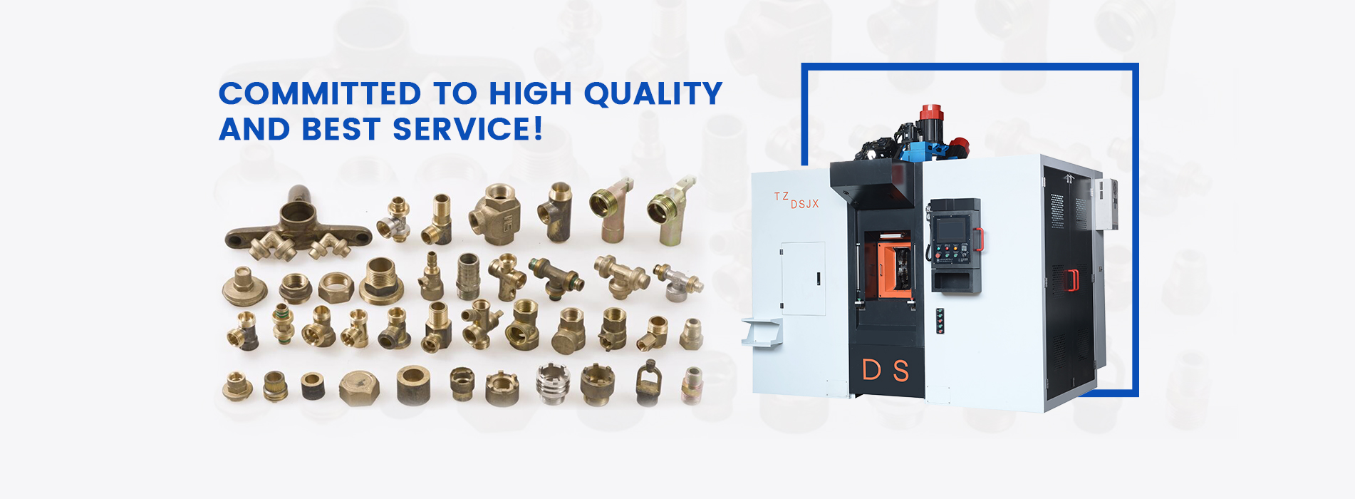
The structure and working principle of CNC milling machine
(1) I/O device. The I/O device is used for the input/output of data such as CNC machining or motion control programs, machining and control data, machine tool parameters, coordinate axis positions, and detection switch states. Keyboard and monitor are necessary and most basic I/O devices for CNC equipment. As the peripheral equipment of the numerical control system, the desktop computer and the portable computer are one of the commonly used I/O devices at present.
(2) Numerical control device. The numerical control device is the core of the numerical control system, which is composed of I/O interface lines, controllers, arithmetic units and memory. The function of the numerical control device is to compile, calculate and process the data input by the input device through the internal logic circuit or control software, and output various information and instructions to control the various parts of the machine tool to perform specified actions.
Among these control information and instructions, the most basic ones are the coordinate axis feed speed, feed direction, and feed displacement instructions generated after interpolation operations, and are provided to the servo drive device. After being amplified by the driver, the final control Axis displacement. These control information and instructions directly determine the movement trajectory of the tool or coordinate axis.
3) Servo drive. Servo drives are usually composed of servo amplifiers (also known as drives, servo units) and actuators. In CNC machine tools, AC servo motors are generally used as actuators. At present, linear motors have been used in advanced high-speed processing machine tools. In addition, among the CNC machine tools produced in the 20th century, there are also simple CNC machine tools using DC servo motors, and stepping motors are also used as actuators. Servo amplifier It must be used in conjunction with the drive motor.
(4) Measuring feedback device. The measurement feedback device is the detection link of the closed-loop (semi-closed-loop) CNC machine tool. Its function is to convert the actuator to Or the actual speed and displacement of the workbench are detected, and fed back to the servo drive device or numerical control device to compensate the feed speed or the motion error of the actuator, so as to achieve the purpose of improving the accuracy of the motion mechanism. The position of the measuring device detection signal feedback depends on the structure of the numerical control system. Servo built-in pulse encoders, tachometers and linear gratings are commonly used detection components.
The advanced servo drive device adopts digital servo drive technology (referred to as digital servo), and the servo drive device and the numerical control device are connected by a bus. In most cases, the feedback signal is connected with the servo drive device and passed through The bus is transmitted to the numerical control device. Only in a few occasions or when an analog control servo drive (abbreviated as analog servo) is used, the feedback device needs to be directly connected to the numerical control device.
(5) Auxiliary control mechanism. The auxiliary control mechanism refers to the control components between the numerical control device, the mechanical components of the machine tool, and the hydraulic components. Its main function is to receive the spindle speed, steering and start-stop commands output by the CNC device, tool selection and exchange commands, start-stop commands for cooling and lubrication devices, loosening and clamping commands for workpieces and machine parts, table indexing, etc. Command signals, as well as signals such as the state of the detection switch on the machine tool, after necessary compilation, logic judgment, and power amplification, directly drive the corresponding actuators, and drive the mechanical components of the machine tool, hydraulic and pneumatic and other auxiliary devices to complete the actions specified in the command. It is usually composed of PLC and a strong current control circuit. PLC can be integrated with CNC in structure (built-in PLC) or relatively independent (external PLC).
6) Machine tool body. The machine tool body is the mechanical structure of the CNC machine tool. It consists of the main transmission system, feed transmission system, bed, worktable, auxiliary motion device, hydraulic/pneumatic system, lubrication system, cooling device, chip removal, protection system, etc. composition. In order to meet the requirements of CNC technology and give full play to the performance of machine tools, compared with ordinary machine tools, CNC machine tools have undergone great changes in the overall layout, appearance, transmission system structure, tool system and operating performance of the machine tool body.
Choose D & S Automatic, we will provide you with the best service.
Copyright © 2025 D&S Automatic Co.,Ltd.. All Rights Reserved.

IPv6 network supported